INNOVATION
New
protected by a patent
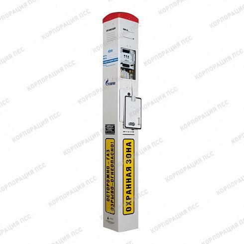
The IPKZ-RA® pulse converter is an equipment used as part of the electrochemical corrosion protection system for underground parts of metal structures. This modification is made in a compact design.
Read more
Description
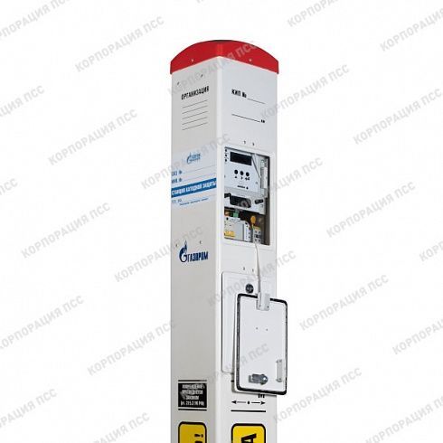
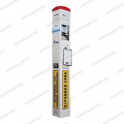
Pulse converter of cathodic protection IPKZ-RA® in the KIP case.PSS is equipment used as part of the electrochemical corrosion protection system for underground parts of metal structures. The device converts alternating electric current into direct current and supplies the necessary potential to the protected elements. IPKZ-RA® is one of the most popular variants of the station used in modern electrochemical protection systems.
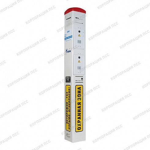
The converter is an equipment unit consisting of a terminal panel, a control system and a power module. The unit is located inside a rack with sealed hatches for working with equipment.
Functionality
It is possible to remotely monitor the operation of the converter and control it using embedded adapters via RS-485 MODBUS RTU interfaces, "current loop" and using a GSM modem.
The converters operate in the following modes:
1) automatic maintenance of the total potential at a given level in the range of values from minus 3.5 V to minus 0.5 V;
2) automatic maintenance of the polarization potential at a given level in the range of values from minus 2.0 V to minus 0.5 V;
3) automatic maintenance of the protective current (stabilization of the output current);
4) automatic stabilization of the output voltage.
Calibration of measuring circuits of the converter control unit was carried out at the manufacturer. The control unit is used as an indicator of the output parameters and operating modes of the converter. To control the correctness of maintaining the set value of the output parameter of the converter, it is necessary to use certified external specialized measuring devices of an approved type that are connected to the corresponding terminals of the converter.
Types of telemetry:
T1 – connection via the "current loop" communication channel with physical signals (analog (4-20 mA) and discrete);
T2 – connection to the converter via serial digital interface RS-485, Modbus RTU protocol;
T3 – connection via GSM/GPRS communication channel version 1 (basic);
T4 – connection via GSM/GPRS communication channel version 2 (with two SIM cards);
T5 – connection via GSM/GPRS communication channel version 3 - (standard type of telemetry for this converter modification);
T6 – connection to the converter via a radio channel (in the UHF band or others).
Combinations of telemetry types can be implemented into converters. In this case, the designation should be carried out as follows:
T13 – combination of T1 and T3 types
T25 – combination of T2 and T5 types
T124 is a combination of types T1, T2 and T4, etc.
The converter is an equipment unit consisting of a terminal panel, a control system and a power module. The unit is located inside a rack with sealed hatches for working with equipment.
Functionality
- Provides measurement of the polarization potential according to GOST 9.602-2016.
- Operation in the mode of automatic maintenance of the total or polarization potentials at a given level.
- Operation in the mode of automatic stabilization of the protective current.
- Operation in the mode of automatic stabilization of the output voltage.
- Alarm about the occurrence of a break in the circuit of the reference electrode or potential sensor with automatic transition to the output current stabilization mode, at the level that was before the accident occurred.
- Calculation and indication of the time when the structure is under cathodic protection.
- Counting and indication of the time when the converters are under the voltage of the supply network, in the switched-on state.
- Short circuit protection in the load circuit with automatic switching to operating mode after the short circuit is eliminated.
- Overload, overvoltage and overheating protection.
- Automatic activation in the set mode when the supply voltage disappears and reappears (in case of power outages).
- The possibility of increasing the output power of the converter by installing additional power modules.
- The input, measuring and output circuits of the converter are protected from pulse overvoltages.
- All information about the output data, operating mode and other parameters of the converter is displayed on the LED display.
- The ability to record (archive) the operating parameters of the converter (input voltage, output voltage and output current of the converter, total and polarization potentials), unauthorized access signals, emergency situations and other signals to a removable SD memory card with a capacity of up to 4 GB installed in the data logger.( This function is not provided as standard, it is discussed when ordering).
It is possible to remotely monitor the operation of the converter and control it using embedded adapters via RS-485 MODBUS RTU interfaces, "current loop" and using a GSM modem.
The converters operate in the following modes:
1) automatic maintenance of the total potential at a given level in the range of values from minus 3.5 V to minus 0.5 V;
2) automatic maintenance of the polarization potential at a given level in the range of values from minus 2.0 V to minus 0.5 V;
3) automatic maintenance of the protective current (stabilization of the output current);
4) automatic stabilization of the output voltage.
Calibration of measuring circuits of the converter control unit was carried out at the manufacturer. The control unit is used as an indicator of the output parameters and operating modes of the converter. To control the correctness of maintaining the set value of the output parameter of the converter, it is necessary to use certified external specialized measuring devices of an approved type that are connected to the corresponding terminals of the converter.
Types of telemetry:
T1 – connection via the "current loop" communication channel with physical signals (analog (4-20 mA) and discrete);
T2 – connection to the converter via serial digital interface RS-485, Modbus RTU protocol;
T3 – connection via GSM/GPRS communication channel version 1 (basic);
T4 – connection via GSM/GPRS communication channel version 2 (with two SIM cards);
T5 – connection via GSM/GPRS communication channel version 3 - (standard type of telemetry for this converter modification);
T6 – connection to the converter via a radio channel (in the UHF band or others).
Combinations of telemetry types can be implemented into converters. In this case, the designation should be carried out as follows:
T13 – combination of T1 and T3 types
T25 – combination of T2 and T5 types
T124 is a combination of types T1, T2 and T4, etc.
How to buy
To purchase equipment, leave a request on the website or contact us:
The manager will contact you to clarify the parameters of the equipment and order details.
The exact cost, terms and conditions of delivery are calculated after filling out a questionnaire or clarifying the requirements for equipment.
The information on the site is only for introductory purposes. Not a public offer.
|
Our experts will answer any question about the product
|
Ask a question
|


